Handshake timing chart — Inspection request, inspection complete and passing the result (sample)
Last updated: 2026-09-23 / Category: Samples, timing charts
A sample of one normal inspection between a PLC and an inspection unit — request, completion and result — drawn in 100 ms steps. For the PLC programmer who does not want to see "the completion never comes back" or "good parts are judged NG" during commissioning.
Open this sample in the editor Download the JSON
The free browser editor opens in a new tab with this chart loaded. No installation, no sign-up, and nothing you enter is sent anywhere. Editing it does not change the sample on this page. The JSON is the source data for reopening it in the editor or handing it to an AI.
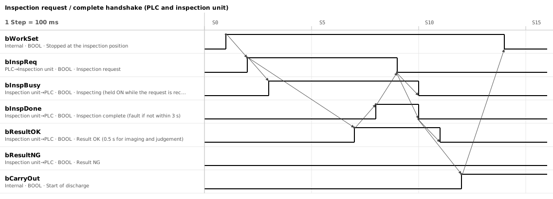
1. Six signals; request and completion drop only after seeing the other side
| Signal | Driven by | Meaning |
|---|---|---|
bWorkSet | PLC (internal) | The part has stopped at the inspection position. Trigger for the request |
bInspReq | PLC → inspection unit | Inspection request. Held until inspection complete turns ON |
bInspBusy | Inspection unit → PLC | Inspecting. Held ON while the request is being received; this tells the PLC the request has arrived |
bInspDone | Inspection unit → PLC | Inspection complete. Held until the request turns OFF |
bResultOK / bResultNG | Inspection unit → PLC | Result. Not changed while inspection complete is ON |
bCarryOut | PLC (internal) | Start of discharge. Raised after seeing inspection complete turn OFF |
The inspection unit is set to hold the completion until the request drops: either the handshake setting of the vision system, or a PLC on the inspection side drives it. A unit left returning the result as a fixed-length pulse will not produce this chart.
Inspecting (bInspBusy) is the acknowledgement that the request was received. It turns ON in the scan after the request and is held until the request drops. If the request is raised and inspecting never comes, the unit is not seeing the request, and a fault can be raised well before the 3 s wait for completion.
2. Arrows fix the order; the only times fixed are 0.5 s and the limits
The changes joined by arrows are spaced one division (100 ms) apart only to show the order. The real responses come back within the scan and communication delay (a few to a few tens of ms). The only times that are fixed are the 0.5 s for imaging and judgement, and the limits in section 4.
- When the part stops at the inspection position, raise the request
- The inspection unit raises the result first, then inspection complete 0.5 s for imaging and judgement.
- The PLC reads the result on the rising edge of the completion, stores it, then drops the request The unit clears the result afterwards. It decides the discharge destination, so keep it in the per-part data (a result bit in the tracking word, for example).
- When the request drops, the unit drops the completion, then the result The reverse of the order they were raised.
- The PLC starts the discharge after seeing inspection complete turn OFF bWorkSet turns OFF as the part leaves.
3. Result before completion; request and completion drop only after seeing the other side
- Raise the result before the completion and drop it after The PLC reads the result on the rising edge of the completion. Even if the unit raises both in the same scan, they do not necessarily reach the PLC together over parallel I/O or a network. Lead by at least the difference in input response times for parallel I/O, or one update cycle for a network.
- Split OK and NG into two points, and treat both OFF as a fault With one point, a wiring fault turns every good part into NG. With a single "ON means OK", a broken result wire makes every good part look NG and they are scrapped until somebody notices. With two points, "completion ON but neither OK nor NG" is caught on the spot and the line stops.
- Hold the request until the completion comes, and the completion until the request drops A pulse gets missed by the other side. Same reason as the "four changes of request and response" in How to draw a timing chart: anything shorter than the receiver's scan or update cycle vanishes before it is seen.
- The next request and the discharge wait for inspection complete to turn OFF So that the previous part's result is not read as this part's. Raise the next request while the completion is still ON and the previous completion and result are read as the current ones. It is also a discharge condition so that a completion that cannot drop (the 1 s in section 4) is caught while the part is still at the inspection position.
4. Put a limit on every wait, and stop with a fault when it is exceeded
Without a limit, the PLC waits forever for the completion when the inspection unit stops, and the line stands still with no reason on the screen.
- Request ON → completion ON — 3 s. The 0.5 s inspection with one retake is about 1 s, so three times that. Also noted in the description of bInspDone in the chart
- Request OFF → completion OFF — 1 s. The unit only has to see the request drop, so it responds within a few scans
An NG result follows the same procedure with bResultNG ON instead of bResultOK. Returning to the home position after a timeout or a unit fault is a different storyline, drawn in a separate timing chart or a How to draw a PLC control flowchart.
5. Three things to change: title, signal names, processing time
After loading it into the Timing Chart Editor with "Open this sample in the editor", change things in this order.
- Title, device names, time per step — "Chart info…" on the toolbar (Ctrl+I). The "(PLC and inspection unit)" in the title stays when the device names change, so fix it here
- Signal names and comments — Double-click a row name. Change the "0.5 s" and "3 s" in the comments to your own values. If your site writes device numbers such as Y100, put them straight into the signal name
- Processing time — Repaint the ON ranges of bResultOK and bInspDone. Arrows are attached to transitions, so redraw them after repainting. If the chart is too short, increase "Steps" on the toolbar or lengthen the time per step
Choose SVG in Output → Export… for a figure to paste into the specification. Press "To the flowchart →" on the toolbar to get a flowchart: the arrows become "which input to wait for before changing which output". You can also download the JSON and have an AI rename the signals to your own convention (JSON format).
The tools this sample was made with
- Timing Chart Editor — The figure above and the sample JSON were made and exported with this editor.
- Flowchart Editor — Turns the arrows of the chart into a sequence of waits and processes.
Related articles
- Air cylinder timing chart (sample)
- Belt conveyor timing chart (sample)
- Servo positioning timing chart (sample)
- How to draw a timing chart
- How to draw a PLC control flowchart
- JSON data format
yk.builds