How to build a PLC address map — Turn the groups of the system diagram into partitions and give each number one writer
Last updated: 2026-09-25 / Category: PLC programming, hardware I/O allocation
An address map is the one table that decides which number is used by whom and for what. This guide is for anyone about to allocate PLC numbers, or sharing numbers with the HMI and drawing people.
1. Drawings, programs and screens are connected only by numbers
The drawings, the PLC program and the touch panel know nothing about each other. All that connects them is a number such as X10 or D200. If nobody owns the rules for those numbers, you get numbers that shift after an addition, and two programs writing the same number.
Both are the kind of accident found during commissioning or after the line has started. An address map decides two things: how the numbers are partitioned, and who writes each number.
2. The two decisions an address map makes
① Turn the groups of the system diagram into memory partitions as they are
The first rule: the groups decided in the system diagram — "Station 1", "Robot", "Operator panel" — become the memory partitions as they are. For each group, decide the device and the number of points, including 10 to 20 percent spare. Numbers are assigned inside that partition.
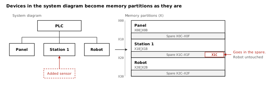
Why it matters — When the physical configuration and the partitions match, an on-site addition stays inside its partition. Add one point to a sequence with no spare and every number after it shifts, and you end up fixing hundreds of references. Partitioned like the system diagram, a sensor added to Station 1 does not move the robot's numbers.
② Give every number exactly one writer
The second rule: declare the writer of each number — "the touch panel writes this partition", "the PLC writes this one". Suppose the touch panel writes the production count to D200, and the program also uses D200 to hold an intermediate result. The count goes wrong now and then, and the screen never tells you which side did it.
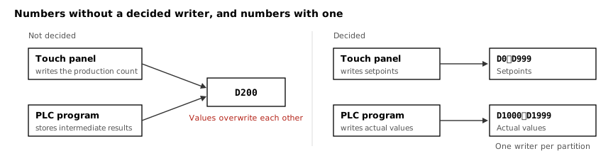
Why it matters — Overwrite bugs are the hardest to find on site. The value only goes wrong when the two writers happen to collide. With the writer in the table, a collision is found while the numbers are being allocated.
3. Rules for I/O, names and 32-bit values
- Assume I/O numbers follow the unit position — Most PLCs number I/O by mounting order and point count. Insert a unit and every number after it shifts. Reserve the slot and points for future units, or fix the numbers in the I/O assignment settings
- Name in the order direction, location, device, signal —
i_Press_TopLSis input, press, top limit switch. Sorted, the signals of one location stay together and are easy to check against the drawings - Give 32-bit values two consecutive words starting at an even number — DINT and REAL take two words. Some touch panels and communication partners assume two-word alignment
4. Example partitions — a table of range and writer for each group of the system diagram
The example uses Mitsubishi Electric notation (I/O numbers in hexadecimal). The partitioning works the same on any PLC.
| Device | Range | Group in the system diagram | Writer | Spare |
|---|---|---|---|---|
| X (inputs) | X000 - X01F | Operator panel switches | Wiring | Last 8 points |
| X (inputs) | X020 - X05F | Station 1 on-machine sensors | Wiring | Last 16 points; each station starts on a new boundary |
| Y (outputs) | Y000 - Y01F | Operator panel lamps and buzzer | PLC | Last 8 points |
| Y (outputs) | Y020 - Y05F | Station 1 solenoid valves | PLC | Up to the largest valve manifold |
| M (internal relays) | M0 - M499 | Operator panel logic | PLC | 20 % |
| M (internal relays) | M500 - M999 | Station 1 automatic operation | PLC | 100 per step |
| M (internal relays) | M1000 - M1199 | Commands to the robot | PLC | 20 % |
| M (internal relays) | M1200 - M1399 | Status from the robot | Robot | 20 % |
| M (internal relays) | M2000 - M2999 | Faults and alarms | PLC | Split into major and minor faults |
| D (data registers) | D0 - D999 | Setpoints | Touch panel | Grouped by product type |
| D (data registers) | D1000 - D1999 | Actual values and monitoring | PLC | 32-bit values start on even numbers |
5. Build in this order: devices → partitions → variables → numbers → check
- Take the devices and blocks from the system diagram PLC, remote I/O, robot, and the groups inside them (units, functions). The system diagram is the source.
- Allocate a partition and spare for each device Decide the device and the number of points for each block first. The count includes the spare.
- Write the writer of each partition Exactly one of PLC, touch panel, robot or wiring.
- List the variables inside each partition and assign numbers They come from the rows of the timing chart or the I/O list from mechanical design. Start 32-bit values on even numbers.
- Check for duplicates and out-of-range numbers, then hand over to the PLC software Export as device comments or labels. Every change of a number starts in the table and flows from the table into the program and the drawings.
6. Where people trip: hexadecimal counting and numbers outside their partition
- Mixing up hexadecimal and decimal — Mitsubishi X and Y are hexadecimal: after
X009comesX00A. Count in decimal and jump toX010, and you are 6 points off. Omron counts in "channel.bit" (0.00to0.15) - Someone uses numbers outside their partition — When several people build the map, assign an owner to each partition. Before using a number outside it, check the table for free space
- Changing a number without going through the table — Change the wiring on site and fix only the drawing, and the table and the program comments stay out of step. Every change starts in the table
Tools for the steps in this article
- Address Map Editor — For each device received from the system diagram, allocate a device and point count to every block. The allocated range appears as empty rows; type a name and it gets its number. Duplicates and out-of-range numbers are detected automatically, and the map exports as device comments or labels to paste into the PLC software.
- System Diagram Editor — Draw the devices and blocks, and use them as the containers of the address map.
- Timing Chart Editor — Draw the order in which the allocated signals change.
No installation, no sign-up. They run in the browser.
Related articles
- How to draw a system diagram
- How to draw a timing chart
- How to draw a PLC control flowchart
- Let AI draw the specification
- JSON data format — The format the four editors read and write, with schema, validation and examples
- How to write a control specification
yk.builds