PLC handling and recovery after an emergency stop — The safety circuit stops; the PLC cleans up and recovers (sample)
Last updated: 2026-09-23 / Category: Samples, flowcharts
What stops the machine on an emergency stop is the safety circuit; a standard PLC handles the clean-up and the recovery procedure. For anyone unsure what the PLC should do after an emergency stop, this flowchart shows the PLC side only.
Open this sample in the editor Download the JSON
The free browser editor opens in a new tab with this flowchart loaded. No installation, no sign-up, and nothing you enter is sent anywhere. Editing it does not change the sample on this page. The JSON is the source data for reopening it in the editor or handing it to an AI (format: JSON data format).
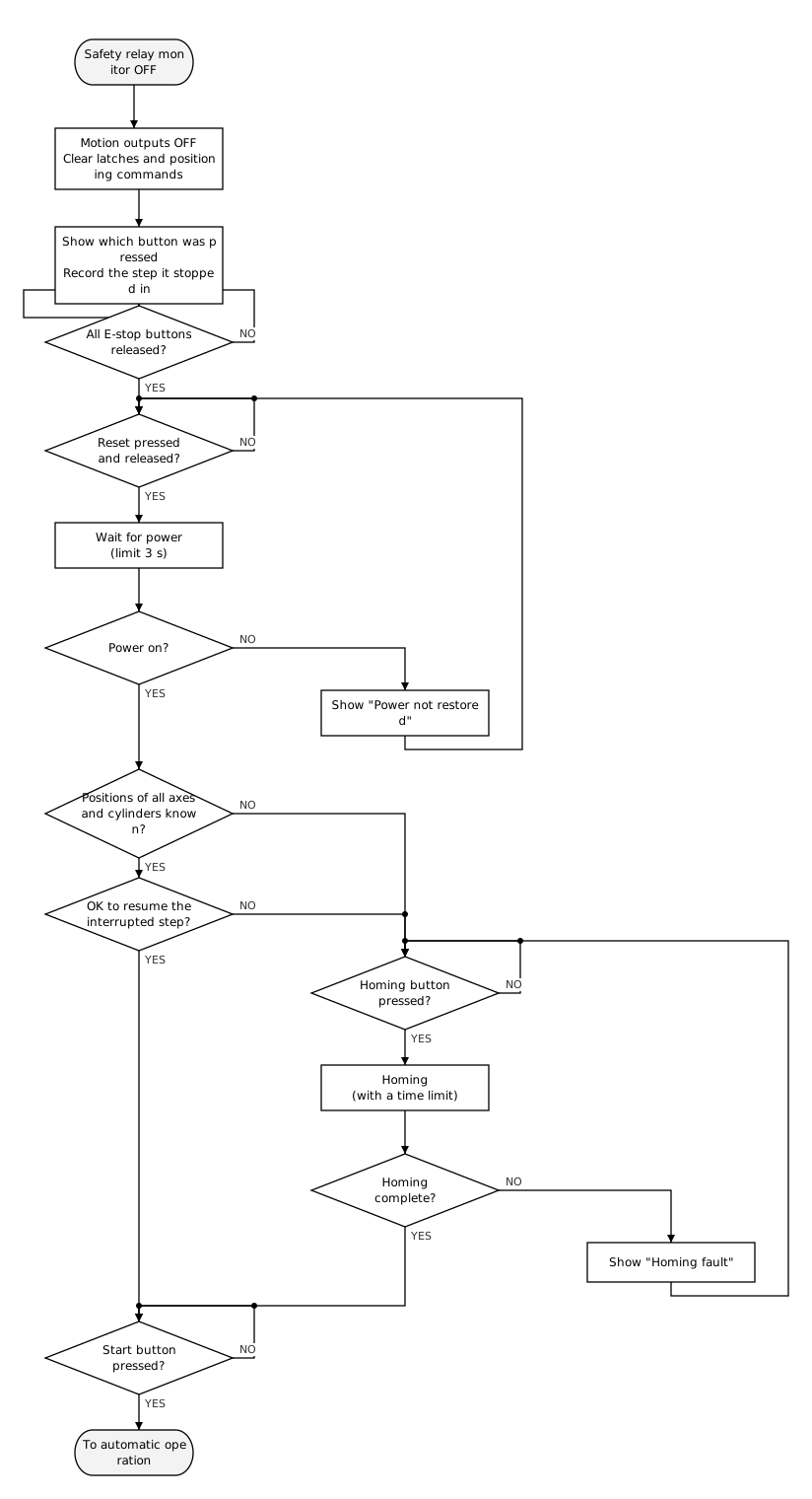
1. The safety circuit stops; this chart is the PLC side only
A standard PLC is not built for safety functions. With an output transistor failed ON, or in the middle of a program download, it cannot be relied on to stop. The safety circuit is designed after a risk assessment, to ISO 13849-1 and IEC 60204-1. This chart is no substitute for it.
- Two ways to stop: stop category 0, cutting the power at once, and category 1, decelerating and then cutting (IEC 60204-1). In both, it is the safety circuit that finally cuts the power. This chart is category 0; for category 1, "command a controlled stop" and "stopped?" go before the first box.
- The first "safety relay monitor": the PLC reads the safety relay's auxiliary contact as an input. The emergency stop button's contact is never wired to the PLC alone.
- "Show which button was pressed": give each emergency stop button a monitoring contact separate from the safety circuit. Wired to the PLC per button, it can show which one was pressed.
- "Reset pressed and released?": the safety relay is set to manual reset. The reset button is wired to the safety relay's reset input, and the PLC reads a second contact of the same button. The PLC also waits for the release because some safety relays accept the reset on the release.
- "Limit 3 s": 3 s is an example, counted from the release of the reset button. Measure the time until the "power on" signal (contactor auxiliary contact, servo ready and so on) comes in, and add a margin. If it never comes, a guard door is still open or a welded contactor contact is stopping the safety relay from accepting the reset.
2. Why this order: give people time to check, and never let the machine start on its own
- Releasing the button, reset and start are three separate operations If releasing the button alone started the machine, it would catch someone else inside it. Reset restores the power and start begins the motion; kept apart, there is time to check the surroundings before anything moves. On the PLC side too, the emergency stop input returning is not a resume condition; it waits for the start button.
- Keep the motion outputs OFF until start or homing The moment the reset restores power, the machine moves according to whatever outputs are left. Clear the remaining outputs and latches, and also the positioning start commands and any remaining travel. Outputs that cause no motion, such as lamps and buzzers, need not be turned OFF.
- What happens when power is cut is decided by the choice of equipment When power or air is cut, clamps and vacuum may release the part. A single-solenoid valve returns to the spring side and vacuum loses its grip, so choose equipment that keeps holding. For a 2-position double solenoid, check which way it moves when the air returns (Air cylinder timing chart (sample)).
- Knowing the positions is not the same as knowing it is safe to continue The state of the part matters as well as the step number. To resume, you also need to know how far the part was processed and whether it is gripped. Decide per step, and write in the specification, that if anything is unknown the machine homes and starts over.
- Homing is started by the operator Started automatically after the reset, the axes would move before the operator is ready. Give homing a time limit too; if it stops partway, show a fault and return to waiting for the homing button. An incremental servo loses its position if even the amplifier's control power is cut, so check how far the emergency stop cuts.
3. The specification states what is cut, how to resume, what is shown, and the time limits
- What the emergency stop cuts (which devices, at which point of the safety circuit), the stop category, and the signals the PLC receives (section 1)
- The outputs not turned OFF, and the choice of equipment that keeps holding when power is cut (items 2 and 3 of section 2)
- How each step resumes (from where it stopped, or home and start over; item 4 of section 2)
- What is displayed (which emergency stop button was pressed, which step it stopped in; section 1)
- The wait for power to return (section 1) and the time limit for homing (Homing flowchart (sample))
The stop and recovery for an opened guard door is drawn almost the same way: the door switch is in the safety circuit, and the order is close the door, reset, start. On a machine a person can enter, whoever goes in takes the door switch key (or their own padlock) with them. If the door must stay shut until the machine has stopped, use an interlocked door and add a stage that unlocks it after confirming the stop.
Once open in the editor, double-click a symbol to change its text.
The tools this sample was made with
- Flowchart Editor — The figure above and the sample JSON were made and exported with this editor.
- Timing Chart Editor — The normal cycle after recovery can be drawn as a timing chart of the signal order.
Related articles
yk.builds