Air cylinder advance and retract timing chart — Watch both "arrived ON" and "left OFF" at each end (sample)
Last updated: 2026-09-23 / Category: Samples, timing charts
A sample of one round trip of an air cylinder with a double solenoid valve and auto switches at the advance and retract ends. For anyone who advanced on timers and found the sequence falling apart the day the speed controllers were tightened.
Open this sample in the editor Download the JSON
The free browser editor opens in a new tab with this chart loaded. No installation, no sign-up, and nothing you enter is sent anywhere. Editing it does not change the sample on this page. The JSON is the source data for reopening it in the editor or handing it to an AI (format: JSON data format).
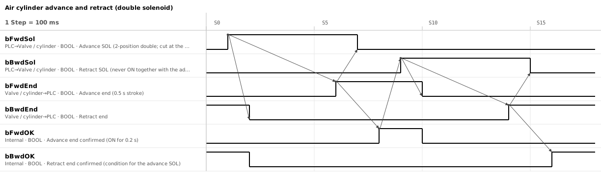
1. The condition for the next motion is the confirmed signal, not the switch itself
| Signal | Direction | Meaning |
|---|---|---|
bFwdSol / bBwdSol | PLC → valve | Advance and retract solenoids (2-position double solenoid) |
bFwdEnd / bBwdEnd | Cylinder → PLC | Auto switches at the advance and retract ends |
bFwdOK / bBwdOK | PLC (internal) | End confirmed. ON when the auto switch has been ON for 0.2 s |
The condition for the next motion is the confirmed signal, not the auto switch itself.
2. Two values to measure: the 0.5 s stroke and the 0.2 s confirmation
- S1: seeing retract-end confirmed, turn the advance SOL ON. At S2 the retract end turns OFF, showing the cylinder has started moving
- S6: advance end ON. At S7 the advance SOL is switched off (the valve stays switched over)
- S8: the advance end has been ON for 0.2 s and is confirmed. The next motion (retract, in this chart) starts here
- S9–S16: the retract works the same way. The advance end turning OFF confirms the start; retract-end confirmed confirms the return
Of the 0.1 s divisions, only these two lengths carry meaning. Both are measured and set during commissioning.
3. Detect the ends with switches, not time, and watch both the arrived ON and the departed OFF
- Whether the end is reached is decided by the auto switch, not by time Time breaks the sequence every time conditions change. "Advance end 0.5 s after advancing" breaks as soon as the air pressure drops or the part gets heavier. Time is used only for the fault monitoring in section 5.
- Watch both the arrived side turning ON and the departed side turning OFF Without the departed side, a cylinder that never starts is invisible. If the advance SOL is on and the retract end does not turn OFF, the supply valve is closed or the solenoid wire is broken. If both ends are ON at once, a switch has shifted or failed.
- Confirm only after the arrived side has been ON for 0.2 s At the moment it turns ON the cylinder is still moving. Even mounted at the catalogue position, an auto switch turns ON about half its operating range before the end. Small cylinders with rubber cushions can bounce at the end and drop the switch for an instant.
4. Never energize both SOLs at once, and write in the specification whether they are cut at the end
- Never turn the advance and retract SOLs ON together A 2-position double solenoid assumes they are never energized at the same time. With both ON, a pilot-operated valve stays where it was, which looks like "the retract SOL is on but it does not come back". Interlock them against each other in the ladder.
- Decide whether to cut the SOL at the end or hold it, and write it in the specification A 2-position double works either way. Cutting reduces heating; holding lets the PLC output monitor show the commanded direction. Even with the SOL cut, the cylinder moves to the side the valve last switched to the moment air is restored.
5. Split the faults into three, so the display alone says where to look
- The departed side does not turn OFF after the SOL is energized: the "does not start" fault. About three times the start-up time measured during commissioning, with a floor of 0.5 s. Re-measure after throttling the speed controllers
- The departed side turned OFF but the arrived side does not turn ON: the "stopped partway" fault. In this sample 2 s from the SOL (four times the 0.5 s stroke). If throttling takes the stroke past 1 s, change this value too
- Both ends ON at once: a switch fault. Stop immediately
They are kept separate so that the display alone tells whether to check the air or the switch positions.
6. Single solenoid, 3-position valve, one-sided switch: three things to read differently
- Single solenoid: one SOL row, and "cut at the end" from section 4 does not apply. The SOL is held while at the advance end, and cutting it is the retract command. A power failure or emergency stop drops the command and the cylinder returns, so check first that the machine is safe moving that way
- 3-position valve: the SOL is not cut at the end. A closed-centre valve may stop short of the end, and an exhaust-centre valve loses force at the end. Cut the SOL only to stop mid-stroke, and even a closed centre cannot hold for long because of compressibility and leakage
- Auto switch on one side only: arrival at the side without a switch can only be assumed from time, so write that time in the specification. Put the switch on the retreat side, where you want to confirm "it is there" before anything else moves. A switch only on the colliding side, watched for OFF, lets a cylinder stopped partway get hit
In a step with several cylinders, add rows to the same chart instead of one chart per cylinder, joining with arrows which confirmation each SOL waits for. In the editor, duplicate a row with Ctrl+D and prefix the name with the function (bClampFwdSol and so on). When the rows pile up, dropping the switch rows and keeping only the SOL and confirmed rows still shows the order of the step.
The tools this sample was made with
- Timing Chart Editor — The figure above and the sample JSON were made and exported with this editor.
- Flowchart Editor — Turns the arrows of the chart into a sequence of waits and processes.
Related articles
- Homing flowchart (sample)
- Emergency stop recovery flowchart (sample)
- Belt conveyor timing chart (sample)
- Servo positioning timing chart (sample)
- How to draw a timing chart
- Handshake timing chart (sample)
- How to draw a PLC control flowchart
yk.builds