Belt conveyor transfer and stop-in-position timing chart — Slow down before stopping (sample)
Last updated: 2026-09-23 / Category: Samples, timing charts
A sample of a part arriving from the previous station on an inverter-driven belt conveyor, slowing down, stopping at the working position and being released. For the conveyor programmer who wants to fix "it stops in a different place every time and the robot misses the part".
Open this sample in the editor Download the JSON
The free browser editor opens in a new tab with this chart loaded. No installation, no sign-up, and nothing you enter is sent anywhere. Editing it does not change the sample on this page. The JSON is the source data for reopening it in the editor or handing it to an AI (format: JSON data format).
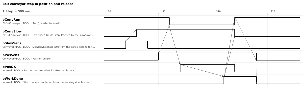
1. Six signals; low speed, confirmed and work done are held in the PLC
| Signal | Direction | Meaning |
|---|---|---|
bConvRun / bConvSlow | PLC → inverter | Run (forward) and low-speed selection (multi-step speed). Low speed latches on the slowdown sensor and is released at the release |
bSlowSens / bPosSens | Sensor → PLC | Slowdown sensor and position sensor. ON while a part is in front of them |
bPosOK | PLC (internal) | Position confirmed. Run has been off for 0.5 s and the position sensor is still ON. Cleared at the release (run ON) |
bWorkDone | PLC (internal) | Work done. The completion from the working side (robot, or the operator's done button), latched. Cleared once the part has left the position sensor |
2. One part: slowdown, stop, confirm, work, release
One division is 0.5 s.
- S2 → S3: switch to low speed when the slowdown sensor turns ON. The part is short, so the sensor turns OFF at S4, but low speed is latched and continues
- S5 → S6: cut run when the position sensor turns ON. The part travels a little further while the inverter decelerates
- S7: 0.5 s after run is cut, if the position sensor is still ON, confirm and start the work. The work takes 2 s
- S11 → S12: on work done, turn run on, release low speed and send the part out at high speed
- S14: once the part has left the position sensor, clear work done and accept the next part
3. Drop to low speed before stopping, and wait 0.5 s before confirming
- Drop to low speed at the slowdown sensor, then stop at the position sensor Stopping at full speed puts the part in a different place every time. The distance travelled after run is cut grows with the square of the speed: half the speed, a quarter of the distance. Measure the overrun from position sensor ON during commissioning and mount the slowdown sensor that far upstream on a slotted bracket.
- Latch low speed and release it at the release Driven straight from the slowdown sensor, it would return to high speed partway. A part shorter than the distance between the two sensors clears the slowdown sensor before reaching the position. Releasing it in the same step as run OFF can command high speed for an instant, depending on which output drops first.
- Confirm the position 0.5 s after run is cut The part keeps moving while it decelerates. Wait until it has stopped, check that the position sensor is still ON, and only then start the work. To detect overrun, add an overrun sensor just past the position.
- Clear work done once the part has left the position sensor Clear it during the release and the same part gets worked on again: if "position sensor ON and not work done" is the stop condition, run is cut again the instant it is cleared. Cleared after the part has left, the next position sensor ON is certainly a new part.
4. Jams, slipping and missing parts are found by limiting the time between sensors
- The position sensor does not turn ON after the slowdown sensor: measure the low-speed travel time during commissioning and set the limit at two to three times that. Causes: the part caught on a guide with the belt slipping under it, the part dropped or removed, a dirty sensor. To tell whether the belt itself slips on the drive pulley, add a proximity sensor watching the idler pulley turn
- The position sensor does not turn OFF after the release: a jam at the exit. Set the limit the same way, from the time one part takes to clear at high speed
If the slowdown sensor is ON when the position is confirmed, the next part has closed the gap. That part never produces a rising edge on the slowdown sensor, so released as it is, it reaches the position sensor at high speed and overruns. Either add "slowdown sensor OFF" to the low-speed release condition, or stop with a fault and stop accepting from the previous station. Keep the gap between parts wider than the sensor spacing minus the part length plus the stopping overrun.
5. Other designs: read the stop method and release conditions differently
- Mechanical positioning: on a roller conveyor that may slip under the part, keep running and stop the part with a stopper. Raising and lowering the stopper follows the Air cylinder timing chart (sample). For accumulation upstream, add a full sensor at the tail of the queue and stop accepting when it stays ON for a few seconds
- Handover to the next conveyor: AND the next station's "ready to accept" into the release condition at S11 → S12. The handover signals take the request and completion form of the Handshake timing chart (sample)
- Brake motor without an inverter: the low-speed row disappears. Cut the motor at the position sensor at full speed and apply the brake (a spring-applied brake engages when the power is cut). The stopping position scatters more than in this chart, by the higher speed and the brake engagement delay
- Stopping position as a number: stop on an encoder value or a servo's in-position instead of the position sensor
The tools this sample was made with
- Timing Chart Editor — The figure above and the sample JSON were made and exported with this editor.
- Flowchart Editor — Turns the arrows of the chart into a sequence of waits and processes.
Related articles
- Servo positioning timing chart (sample)
- How to draw a timing chart
- Air cylinder timing chart (sample)
- Handshake timing chart (sample)
yk.builds